Using Symbolic Execution to Devirtualise a Virtualised Binary
Today I will be discussing a sample binary which features virtual machine obfuscation, an obfuscation technique where the source code is compiled to a custom bytecode language and executed by an interpreter for this language. I will not be covering the basics of how VM obfuscation works; if you would like to read about that there are plenty of good resources online such as this.
The sample is fsvm from openECSC 2024, however note I did not complete it as a CTF challenge; instead I am using it retrospectively as a good example of basic VM obfuscation. Thanks to SteakEnthusiast for the recommendation.
The sample is a Linux x64 binary. The main function looks like:
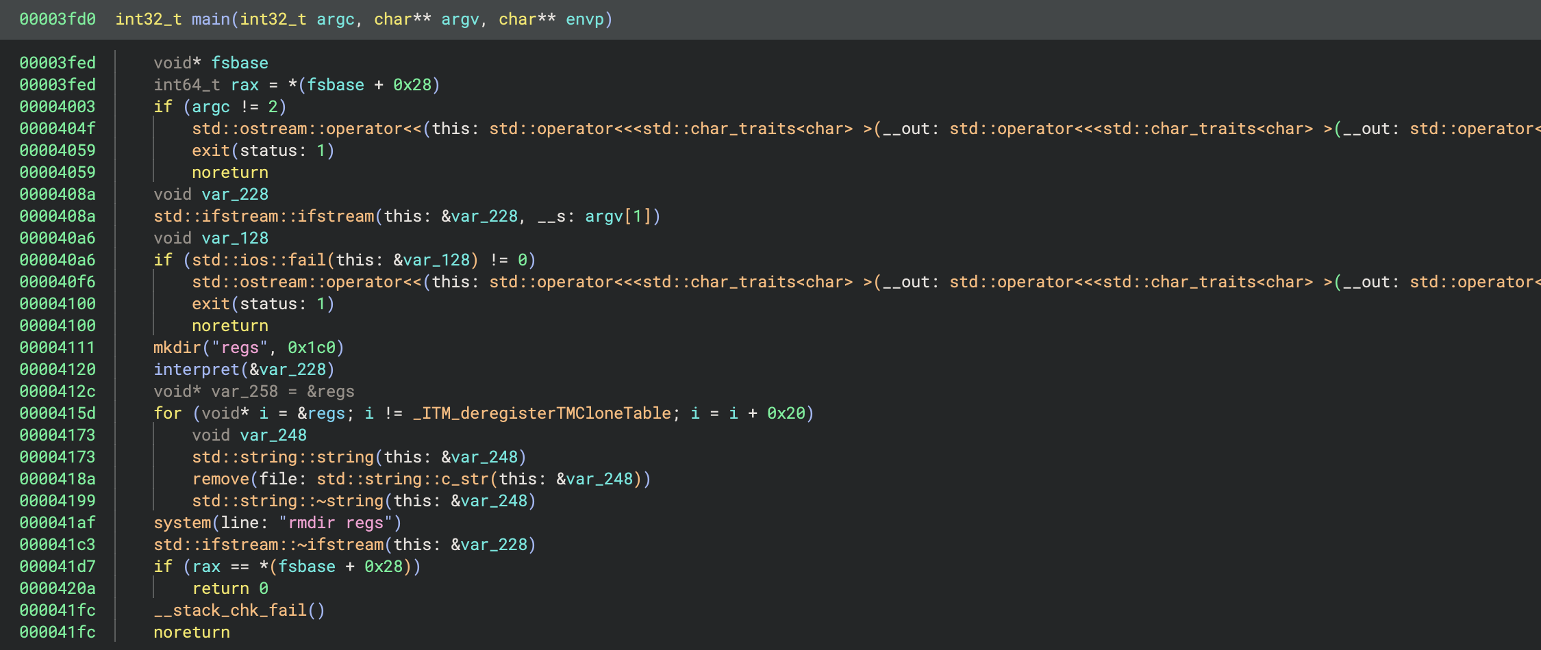
The first conditional checks that the path to a bytecode file has been provided as an argument, and if not prints an error message. A file named bytecode is provided (with seemingly garbled contents), so we can use this.
The bytecode file is then read in as a file stream in variable var_228. Next a directory named regs is created and the interpret function is invoked with our bytecode stream as a parameter. Afterwards it deletes some files from within the regs directory (note that Binary Ninja has missed the last argument i to the string calls), and finally removes the regs directory.
regs, which we rename to reg0 later on, is a 32-byte memory section, which is immediately followed by another 32-byte memory section reg1 and so on. During an initialisation routine these sections are set to strings with according filenames, e.g. regs/reg0. So via iterating over ®s + i we are accessing the name of each of these filenames.
The name of the regs directory and files within it suggest that these files might be VM registers. Similarly the naming of the interpret function tells us it is most likely the main VM loop function, often known as the dispatcher.
Jumping to interpret reveals a loop with a large switch statement inside. The control flow graph of this function looks like:
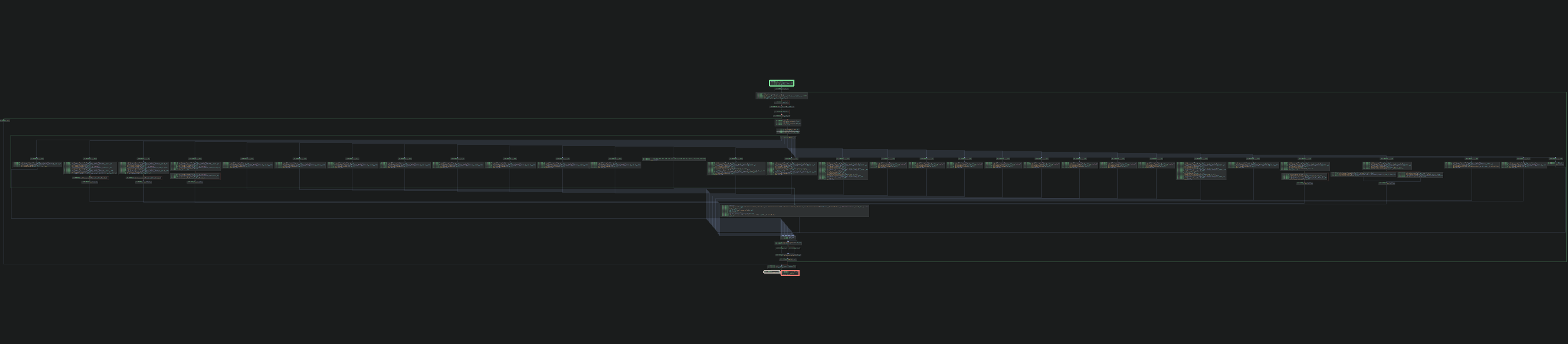
This is exactly what we’d expect for a VM (or alternatively control flow flattening). At the start of the loop the program reads the next character from the bytecode stream and performs a switch based upon it. Clearly this is the opcode.
Each case within the switch is a VM handler, each of which executes a different instruction. There are handlers for opcodes from 40-87, although strangely opcodes 52-60 and 72-80 don’t exist.
From reading through the handlers, we can tell that the VM has 8 registers, named reg0 through reg7. The instruction pointer is represented as the position in the bytecode stream.
There are a number of handlers which perform simple operations, such as clearing a specific register:
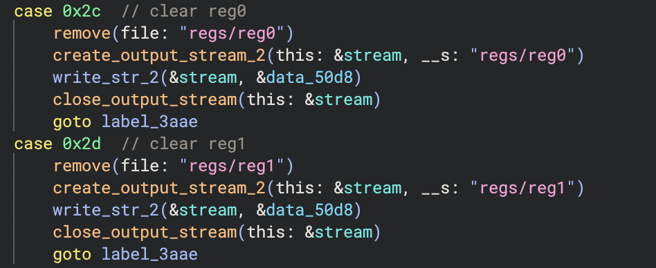
Note that I have renamed the string and file stream related functions for clarity. There are also handlers for writing values to registers, adding two registers together, accessing the last character of strings and both fixed and conditional jumps.
The add handler looks like:
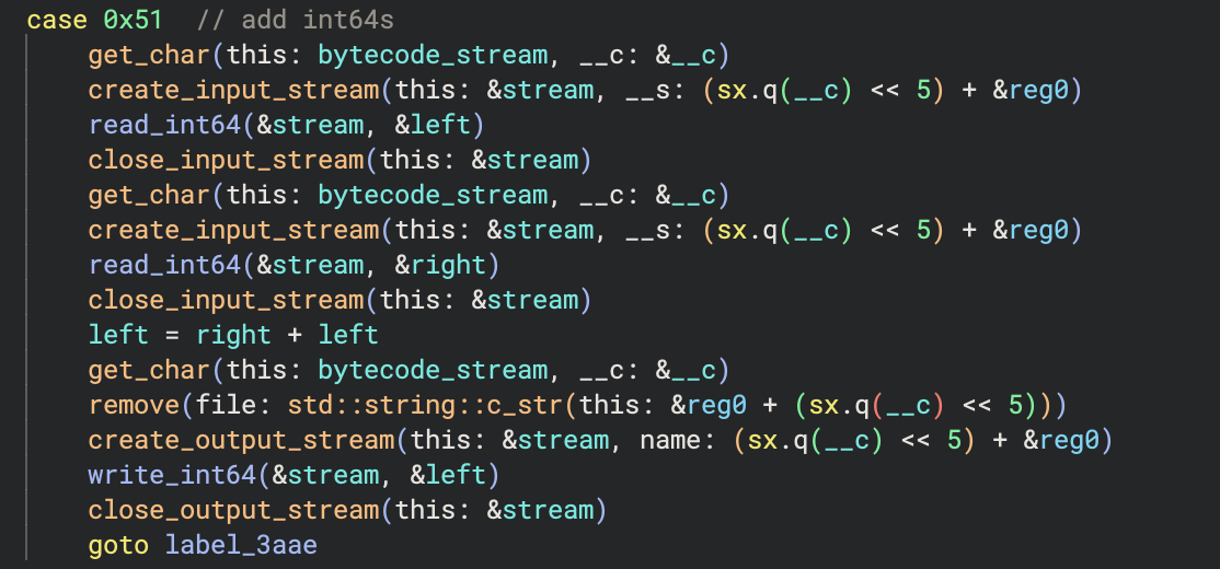
Notice that to access a register, the VM reads the register index then left shifts by 5 (so multiplies by 32) and adds it to a pointer to reg0. Recall that reg0, reg1, etc. are contiguous memory sections, so this is accessing the according register filename. For example 1 would become ®0 + 32, which is a pointer to ®1 (and which is then the string "regs/reg1").
Since the registers are files they can hold several characters; in some cases handlers will overwrite the current value(s) in the register and others will append characters to the end of the file. Some handlers interpret the contents of registers as numbers rather than strings, so 00110 will be read as the int value 110.
A list of the instructions can be found below.
| Opcode | Instruction | Description |
|---|---|---|
| 0x28 | jmp | Fixed jump (to relative offset) |
| 0x29 | je | Jump if equal (to relative offset) |
| 0x2a | jne | Jump if not equal (to relative offset) |
| 0x2b | jl | Jump if less than (to relative offset) |
| 0x2c - 0x33 | clear | Clear reg0 - reg7 |
| 0x3d | write_last_char_code | Writes the last char code of one register to another |
| 0x3e | write_char | Writes the char given by the int value in one register to another |
| 0x3f | concat_strings | Concatenates two registers as strings |
| 0x40 - 0x47 | set_zero | Sets reg0 - reg7 to the char '0' |
| 0x51 | add | Adds two registers together |
| 0x52 | append_one | Appends the char '1' to a register |
| 0x53 | pop_last_char | Pops the last char of a register |
| 0x54 | invert_sign | Inverts the sign of a register |
| 0x55 | Prints a string to stdout | |
| 0x56 | read | Reads a string from stdin |
| 0x57 | ret | Returns from the VM |
Disassembling
Now that we understand the VM’s architecture, we can write a disassembler. This is a fairly straightforward process for this sample, and I have shown examples in previous articles so I won’t go into detail here. The source code for the disassembler can be found here.
This produces output which looks like:
0x0:	set                   reg0, 0
0x1:	append                reg0, 1
0x3:	add                   reg0, reg0, reg0
0x7:	set                   reg1, 0
0x8:	add                   reg1, reg0, reg1
0xc:	add                   reg0, reg0, reg0
0x10:	add                   reg0, reg0, reg0
0x14:	add                   reg0, reg0, reg1
0x18:	set                   reg2, 0
0x19:	append                reg2, 1
0x1b:	add                   reg2, reg2, reg2
0x1f:	concat_strings        reg4, reg0, reg2
0x23:	write_char            reg4, reg4
0x26:	add                   reg2, reg2, reg2
0x2a:	add                   reg2, reg2, reg2
0x2e:	concat_strings        reg2, reg0, reg2
...
The full disassembly can be found here.
If we analyse the disassembly we can see it appends and adds 0s and 1s together then converts them to a character. It does this repeatedly to build the string "flag:", then prints it out. Next it reads the flag from the user and stores it in reg0.
Then there is a long section which appears confusing at first, but once you stare at it a pattern emerges. A group of instructions similar to the following is repeated:
0xaf:	set                   reg1, 0
0xb0:	append                reg1, 1
0xb2:	set                   reg2, 0
0xb3:	add                   reg2, reg1, reg2
0xb7:	append                reg1, 1
0xb9:	add                   reg1, reg1, reg2
0xbd:	set                   reg2, 0
0xbe:	append                reg2, 1
0xc0:	set                   reg3, 0
0xc1:	add                   reg3, reg2, reg3
0xc5:	add                   reg2, reg2, reg2
0xc9:	add                   reg2, reg2, reg2
0xcd:	add                   reg2, reg2, reg3
0xd1:	concat_strings        reg1, reg1, reg2
0xd5:	write_last_char_code  reg2, reg0
0xd8:	pop_last_char         reg0
0xda:	invert_sign           reg2
0xdc:	add                   reg2, reg2, reg1
0xe0:	concat_strings        reg6, reg2, reg6
0xe4:	concat_strings        reg7, reg5, reg7
It first uses set, append, and add instructions to create some number (these instructions differ between groups). Next it accesses the last char code of the flag (remember we stored it in reg0) and removes the last character of the flag. It inverts the sign of the flag char code and adds it to the number it created earlier, 125 - char in this case. It appends this result to reg6 and also appends a zero to reg5.
Intuition suggests that each section is validating a character from the flag. Indeed, 125 is the character code for '}', which is what we’d expect as each section pops the last character from the flag so we are validating in reverse.
After the repeated groups, the result string in reg6 is compared to the zero string in reg5 (which is '0' repeated for each flag character we validated). If the strings match then it prints "ok" otherwise it prints "no".
This knowledge alone is enough to solve the challenge: one could manually repeat the same static analysis for each group of instructions or dump each expected char code output dynamically (e.g. via a gdb script). However this is a good use case for using symbolic execution to recover devirtualised pseudocode from the binary, and obtain the flag along with it.
Symbolic Execution
Symbolic execution is a technique of simulating a program using symbolic values, or symbols. Instead of executing the program as normal with concrete input, we treat variables (and other unknowns) as symbols which can take a range of possible values. We follow all possible paths in the program in order to explore every possible execution path.
Symbolic execution has a number of use cases, most commonly analysing programs to identify bugs. When using symbolic execution in production you’ll almost always be using an existing library to handle the underlying concepts, however in this case we want to simulate our own custom instruction set produced by the disassembler so we will build our own mini symbolic execution tool.
Another difference between what we will build and complete libraries used in production is that they will typically make use of a theorem prover (such as an SMT solver) to check the constraints for each path being simulated. For example if there is a conditional with a % 2 == 0 then the solver will tell us that within the body of the conditional the symbol a is constrained to being even. This is very useful as it allows you to determine which range of inputs causes a program to reach a specific state, however we already know from our previous analysis that the virtualised program is pretty simple so we won’t bother with a theorem prover.
Note: Libraries such as angr have become popular with reverse engineers/CTF players who want to provide an address and determine which input caused the program to reach it (e.g. the flag in the case of CTF challenges).
To represent symbols we use a base symbol class, and have more specialised descendants such as string symbols. We also implement symbols to represent combinations/operations on other symbols (or combinations of symbolic and concrete values), such as unary (e.g. -a) and binary expressions (e.g. a + b). Symbolic execution tools often refer to these symbols (or any symbols in general) as ASTs. The implementations of the symbols can be found here.
We also create classes to represent a state, which is a single execution path, and the execution manager, which is in charge of managing all the states in the program and continuing to explore until all states have terminated (or errored). Each state holds its current position and its own set of registers (which are the symbols in each register).
Since our goal is to obtain pseudocode of the original (devirtualised) program, we also maintain a CFG (control flow graph) which holds the statements of the pseudocode we build. We store a CFG for each state, and will merge them later to create the overall pseudocode. As we symbolically execute each state, we add statements to the graph. If we add a new statement for each instruction, we will end up with very long output not dissimilar from the disassembly, e.g.
a = 5
c = a + some_var
d = c * 2
e = d - 27
print e
However the beauty of symbolic execution for this purpose is that we can allow it to do all the work for us, and only add new statements when something important happens, such as printing a message in this example. This will result in:
print ((5 + some_var) * 2) - 27
This allows us to obtain very clean pseudocode without worrying about compiler optimisations as the classic decompiler approach would. In the case of our program, we add statements when there are syscalls (such as puts and scanf), conditionals/branching and when a state returns.
When a conditional jump occurs, which are je, jne, and jl for our instruction set, we create two new states and explore both simultaneously.
Example
Let’s follow through the example from before. Feel free to skip over this section if you are familiar with symbolic execution. Note that this could be considered concolic execution, as instead of keeping everything symbolic, we will simplify expressions where possible (e.g. resolve 010 + 1 to 11).
0xaf:	set                   reg1, 0
0xb0:	append                reg1, 1
0xb2:	set                   reg2, 0
0xb3:	add                   reg2, reg1, reg2
0xb7:	append                reg1, 1
0xb9:	add                   reg1, reg1, reg2
0xbd:	set                   reg2, 0
0xbe:	append                reg2, 1
0xc0:	set                   reg3, 0
0xc1:	add                   reg3, reg2, reg3
0xc5:	add                   reg2, reg2, reg2
0xc9:	add                   reg2, reg2, reg2
0xcd:	add                   reg2, reg2, reg3
0xd1:	concat_strings        reg1, reg1, reg2
0xd5:	write_last_char_code  reg2, reg0
0xd8:	pop_last_char         reg0
0xda:	invert_sign           reg2
0xdc:	add                   reg2, reg2, reg1
0xe0:	concat_strings        reg6, reg2, reg6
0xe4:	concat_strings        reg7, reg5, reg7
| IP | reg0 | reg1 | reg2 | reg3 | reg6 | reg7 |
|---|---|---|---|---|---|---|
| 0xaf | flag | <empty> | <empty> | <empty> | <empty> | <empty> |
| 0xb0 | flag | 0 | <empty> | <empty> | <empty> | <empty> |
| 0xb2 | flag | 01 | <empty> | <empty> | <empty> | <empty> |
| 0xb3 | flag | 01 | 0 | <empty> | <empty> | <empty> |
| 0xb7 | flag | 01 | 1 | <empty> | <empty> | <empty> |
| 0xb9 | flag | 011 | 1 | <empty> | <empty> | <empty> |
| 0xbd | flag | 12 | 1 | <empty> | <empty> | <empty> |
| 0xbe | flag | 12 | 0 | <empty> | <empty> | <empty> |
| 0xc0 | flag | 12 | 01 | <empty> | <empty> | <empty> |
| 0xc1 | flag | 12 | 01 | 0 | <empty> | <empty> |
| 0xc5 | flag | 12 | 01 | 1 | <empty> | <empty> |
| 0xc9 | flag | 12 | 2 | 1 | <empty> | <empty> |
| 0xcd | flag | 12 | 4 | 1 | <empty> | <empty> |
| 0xd1 | flag | 12 | 5 | 1 | <empty> | <empty> |
| 0xd5 | flag | 125 | 5 | 1 | <empty> | <empty> |
| 0xd8 | flag | 125 | flag[28] | 1 | <empty> | <empty> |
| 0xda | flag[0:28] | 125 | flag[28] | 1 | <empty> | <empty> |
| 0xdc | flag[0:28] | 125 | -flag[28] | 1 | <empty> | <empty> |
| 0xe0 | flag[0:28] | 125 | -flag[28] + 125 | 1 | <empty> | <empty> |
| 0xe4 | flag[0:28] | 125 | -flag[28] + 125 | 1 | -flag[28] + 125 | <empty> |
| 0xe8 | flag[0:28] | 125 | -flag[28] + 125 | 1 | -flag[28] + 125 | 0 |
Recall reg6 and reg7 were where the result string and expected string (all zeros) were stored respectively. This process repeats for the rest of the flag, and eventually compares the result and expected strings.
Generating pseudocode
Once all states have terminated, we can combine the CFGs produced by each state together to form the resultant graph. Finally we have to generate code from the CFG; usually this is a complex process involving graph theory however in our case we only have simple conditionals with branches that both terminate, so we don’t need to worry about this.
I also constrained the input (which is the flag) to be 29 characters long, which I determined from the disassembly. The reason for this is it provides better output, as we will have a concrete value for the index of any flag characters being accessed, rather than having to use flag[flag.length - x].
The resultant pseudo-C code is:
#include <stdio.h>

int main(int argc, char* argv[]) {
	puts("flag:");
	char flag[29];
	scanf("%s", flag);
	if ((((-flag[0]) + 111) + (((-flag[1]) + 112) + (((-flag[2]) + 101) + (((-flag[3]) + 110) + (((-flag[4]) + 69) + (((-flag[5]) + 67) + (((-flag[6]) + 83) + (((-flag[7]) + 67) + (((-flag[8]) + 123) + (((-flag[9]) + 115) + (((-flag[10]) + 117) + (((-flag[11]) + 112) + (((-flag[12]) + 101) + (((-flag[13]) + 114) + (((-flag[14]) + 101) + (((-flag[15]) + 97) + (((-flag[16]) + 115) + (((-flag[17]) + 121) + (((-flag[18]) + 118) + (((-flag[19]) + 109) + (((-flag[20]) + 99) + (((-flag[21]) + 52) + (((-flag[22]) + 101) + (((-flag[23]) + 56) + (((-flag[24]) + 55) + (((-flag[25]) + 99) + (((-flag[26]) + 52) + (((-flag[27]) + 100) + ((-flag[28]) + 125))))))))))))))))))))))))))))) != "00000000000000000000000000000") {
		puts("no");
		return 0;
	} else {
		puts("ok");
		return 0;
	}
}
I say pseudo-C as this is (very much) not valid C code, however it could be made so without too much effort. I chose to represent it like this as it’s pretty easy to read and is a common target for decompilation.
If we look at the if statement condition we can see exactly what we observed when manually analysing the disassembly: the program transforms each character by a fixed amount and checks if any of them are non-zero. If so then the flag was wrong, otherwise it was the correct one.
We can now read the flag characters out by hand, although I included a file in the repo which uses a regex to extract and print the flag:
openECSC{supereasyvmc4e87c4d}
Epilogue
The binary and bytecode for the challenge can be found here.
The repo containing the disassembler and symbolic executor is here.
Please note that I am by no means in expert in symbolic execution. If you would like to understand the more complicated parts which we didn’t have to deal with, such as merging states and avoiding path explosion, I would recommend reading some papers on it. A good list can be found here. The purpose of this article is to demonstrate a lesser-known application of symbolic execution, and one which has worked well in previous reverse engineering projects for me.
If you would like to provide feedback on this article, or discuss any part of it please email me at bensb1@protonmail.com.